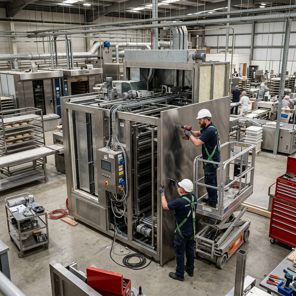
The oven expansion was approved, installed, and ready to run. Bakery proofer replacement at the component level is the solution production directors are discovering after downstream investments fall short of expected gains. The throughput projections have yet to materialize, and the explanation sits upstream in the proofer.
Your proofer is running, trays are moving, and product is coming through. The system appears fully operational, trays advance continuously, and product proofs correctly on each cycle. A traveling tray proofer operating below its rated capacity looks identical to one performing at full output.
The downstream investment in oven capacity and staffing is ready to perform. The production ceiling lies in the proofer, driven by accumulated component wear across rollers, axle pins, sprockets, and fingers. Targeted component-level replacement removes that ceiling and unlocks the volume your expanded operations can deliver.
Bottleneck Mechanism One: Worn Rollers Reducing the System’s Achievable Tray Speed
Roller wear is the most direct mechanical pathway from component degradation to reduced tray movement speed in a traveling tray proofer. Worn rollers increase resistance at every tray contact point in the conveyor path, and the drive system responds by reducing effective tray speed to maintain stable movement. The system settles at a tray speed limited by the degraded roller resistance, which falls below the rated capacity.
Fewer trays complete the proofing cycle per shift, leaving the downstream oven underutilized despite being fully operational. BEW Nylatron Roller and Type F Roller (SKU 001-003) bakery proofer replacement restores roller contact profile and bearing resistance to specification, eliminating the resistance-driven speed ceiling. The oven begins receiving product at the rate it was designed to process.
Bottleneck Mechanism Two: Worn Axle Pins Forcing Operating Speed Reduction to Prevent Tray Interference
Worn axle pins cause tray instability and lateral movement, forcing the proofer to operate at reduced tray speeds. At higher speeds, the lateral movement of trays on worn axle pins creates tray-on-tray interference that damages product and risks mechanical jam. The system runs at a protective speed to keep trays stable and product intact.
Axle pins secure the tray in position and maintain its alignment along the conveyor path. As pin wear increases, lateral play in the tray mounting causes trays to move with slight lateral oscillation at higher speeds. In sections where tray spacing is tight, this creates a risk of product-to-tray interference and tray-to-tray contact.
Full axle pin set replacement across the tray population, including Type ‘N’ S/S (003-000), Type ‘O’ S/S (003-002), BEW Axle S/S (008-000), BP Axle (006-006), and BP Tray Center Pin (003-007), restores tray stability. This bakery proofer replacement program removes the speed ceiling imposed by instability management. The proofer recovers its full tray throughput capacity once pins are restored to specification.
Bottleneck Mechanism Three: Sprocket and Hub Wear Creating Drive Irregularity at Higher Throughput Rates
The Sprocket Assembly with Phase-lok Hub (S-006) and Phase-lok Hub (012-001) are the mechanical heart of the tray drive system. Sprocket assembly and hub wear cause chain slip and irregular drive cadence, which become production-limiting at higher tray throughput rates. As the sprocket tooth profile wears and hub engagement degrades, the precision of chain-to-sprocket engagement decreases, leading to micro-slip events and cadence variation.
These effects remain imperceptible at low speeds and create significant irregularities in tray spacing at higher throughput rates, leading to product overlap risk at entry points and tray-to-tray contact. Sprocket Assembly with Phase-lok Hub (S-006), Phase-lok Hub (012-001), and Removable Hub (009-003A) bakery proofer replacement restores drive precision and removes the cadence ceiling. The proofer enables the tray throughput required by your production targets.
Bottleneck Mechanism Four: Worn Fingers and Endplates Limiting Product Handoff Speed at Entry and Exit
Worn proofer fingers and endplates create irregularities in product handling at the proofer’s entry and exit points. The proofer moves trays through the proofing cycle at higher speeds, and the product handoff rate remains limited by the precision of the fingers and endplates that it can deliver. This is where bakery proofer replacement at the handoff components becomes critical to full-speed operation.
Middle Fingers (PMF-004) and Tray End Fingers (PEF-003) guide product onto and off trays at the proofer entry and exit points. As finger geometry wears, the precision of product placement decreases, and at higher throughput rates, worn fingers produce misplacement events. Speed reduction is used to maintain product placement within an acceptable tolerance.
Endplate wear (32″ Endplate PEP-003) affects tray structural integrity at the system boundary and limits how cleanly the product is received and discharged at higher rates. Finger and endplate replacement restores handoff geometry precision and removes the ceiling on entry and exit throughput. Your proofer gains the ability to feed product to the downstream oven line at the pace it was installed to handle.
How Bakery Proofer Replacement Removes the Capacity Ceiling
A traveling tray proofer running below rated capacity due to accumulated roller, axle pin, sprocket, and finger wear is a production ceiling your facility can remove. Your oven capacity is already installed, your staffing is in place, and the volume your customer relationships require is available. Bakery proofer replacement at the component level makes all of that investment perform.
FBS carries rollers, axle pins, sprocket assemblies, hubs, fingers, and endplates for Latendorf, BEW, and Baker Perkins traveling tray proofer systems, with custom fabrication available for non-standard components. Whether you are addressing a single mechanical ceiling or building a full component replacement program, FBS has the parts and expertise to support your throughput targets. Call +1 (201) 437-0221 to discuss a component replacement program built around your production goals.
Frequently Asked Questions
How do worn proofer rollers reduce production throughput in commercial bakeries?
Worn rollers increase resistance at every tray contact point along the conveyor path, forcing the drive system to reduce tray speed to maintain stable movement. Fewer trays complete the proofing cycle per hour, leaving the oven downstream running below utilization. Bakery proofer replacement with new rollers restores contact profile and bearing resistance to specification, allowing the proofer to deliver trays at its rated rate.
Can worn proofer axle pins limit production speed and throughput?
Worn axle pins allow lateral tray movement, creating interference at higher speeds, prompting operators to run the proofer at a reduced protective speed. Full axle pin replacement across the tray population restores alignment precision and removes this imposed speed ceiling. The proofer recovers its full tray throughput capacity once pins are restored to specification.
How does sprocket wear limit traveling tray proofer throughput speed?
As sprocket tooth profiles wear and hub engagement degrades, the drive system produces micro-slip events and tray cadence variation that grow pronounced at higher speeds. Irregular tray spacing follows, creating an interference risk that forces the system to run below rated capacity. Sprocket assembly and hub replacement restore the drive precision required for full-speed operation.
How do worn proofer fingers affect production throughput and product handling speed?
Worn finger geometry reduces placement precision at the proofer entry and exit, causing misplacement events at higher throughput rates that require speed reduction to control. Replacing fingers and endplates restores the handoff accuracy needed to run the system at rated capacity. Your proofer gains the ability to deliver product to the oven line at the pace the downstream equipment is designed to receive.
Why does oven capacity expansion deliver full results only after proofer components are addressed?
When the proofer delivers product below the rated speed due to component wear, the downstream oven capacity receives product at a reduced rate. The throughput constraint is upstream, and oven expansion delivers its full benefit after the proofer’s mechanical ceiling is removed. A targeted bakery proofer replacement program addresses that constraint at the source.
What is the difference between proofer component replacement and full proofer replacement?
Component-level replacement addresses specific worn parts such as rollers, axle pins, sprockets, fingers, and endplates while the proofer’s structural and mechanical infrastructure remains intact. Full system replacement is appropriate when structural integrity has failed. When throughput loss is driven by component wear on a mechanically sound frame, bakery proofer replacement at the component level delivers the capacity gain at a lower overall investment.
How do we know if our traveling tray proofer is running below rated capacity?
A proofer running below capacity operates quietly, advances trays continuously, and proofs product correctly on each cycle. The indicator is the gap between your proofer’s rated tray throughput and your actual tray count per shift. Oven utilization remaining below capacity during continuous production runs is a clear signal that a component ceiling is present.
What proofer brands does FBS supply replacement components for?
FBS carries replacement components for Latendorf, BEW, and Baker Perkins traveling tray proofer systems. The range includes rollers, axle pins, sprocket assemblies, Phase-lok hubs, fingers, and endplates. Custom fabrication is available for non-standard or out-of-production components.
How long does a traveling tray proofer component replacement program take to implement?
Component-level replacement is designed to work within planned downtime windows, making implementation timelines compatible with ongoing production schedules. Full system replacement requires extended shutdown periods, while component programs align with scheduled maintenance windows. FBS can structure a program around your throughput targets and scheduling constraints.
Which components should be replaced first when addressing a proofer throughput ceiling?
Rollers and axle pins are the highest-impact starting points, as these govern tray speed and stability most consistently. Sprocket assemblies and fingers address secondary constraints that become limiting once roller and pin wear is corrected. A review of tray speed performance, lateral stability, and drive cadence will identify which components form the active ceiling in your specific system.